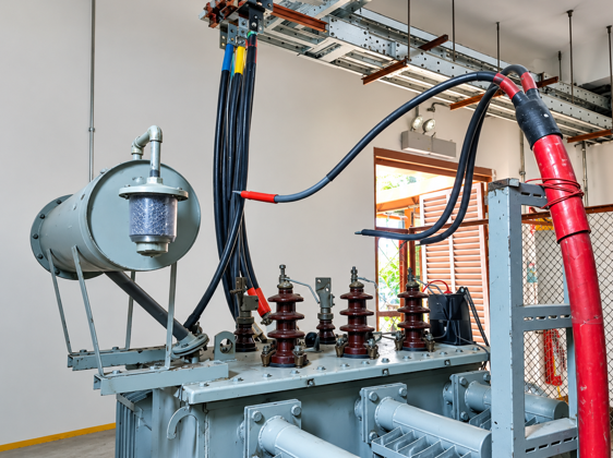
Electrical power systems require a reliable grounding arrangement to control fault currents, protect equipment, and support the operation of protective relays. In networks where the transformer winding configuration does not provide a suitable neutral point, an earthing transformer can establish an artificial neutral for grounding purposes.
A zigzag earthing transformer is designed specifically for this task. It provides a grounding path during earth faults while presenting a high impedance to balanced, normal three-phase currents. This arrangement helps electrical engineers manage ground-fault conditions without requiring a dedicated neutral connection from the main power transformer.
These transformers are used in industrial distribution systems, renewable energy installations, substations, and medium-voltage networks where reliable earth-fault protection is necessary.


How a Zigzag Earthing Transformer Works
The operating principle depends on a specially arranged three-phase winding configuration. Each phase typically has two winding sections positioned on different core limbs. Their electrical connections create a zigzag pattern that allows the transformer to establish a neutral point.
Under normal balanced operating conditions, the magnetic effects associated with the three phases largely cancel. Consequently, the transformer draws relatively little current, apart from its normal excitation current and other operating losses.
During a single-line-to-ground fault, the three-phase currents become unbalanced. The transformer provides a path for zero-sequence current, allowing the grounding system and protective relays to respond to the fault.
The grounding current depends on the system design, transformer impedance, and any additional grounding impedance. Some installations connect a neutral grounding resistor between the artificial neutral and earth to limit fault current to a predetermined value.
This configuration must be engineered to withstand the expected fault-current magnitude and duration. Incorrect sizing can lead to overheating, insulation damage, or inadequate protection during an earth fault.
See also: How Patio Furniture Assembly Can Transform Your Outdoor Space
Where Earthing Transformers Are Used
Earthing transformers are useful in networks that lack an accessible neutral point or require a dedicated grounding arrangement.
Common applications include:
- Industrial plants: Factories with medium-voltage distribution networks use grounding transformers to support earth-fault detection and equipment protection.
- Renewable energy projects: Wind farms and solar power plants may require grounding arrangements compatible with their collector networks and transformer connections.
- Electrical substations: Utilities use these transformers where network configurations need an artificial neutral for controlled grounding.
- Mining and processing facilities: Proper grounding helps manage electrical faults in demanding industrial environments.
- Isolated distribution networks: Systems with delta-connected windings can use an earthing transformer to provide a neutral grounding point.
The exact arrangement depends on the system voltage, grounding philosophy, available fault current, and applicable electrical standards. An earthing transformer should not be selected solely because a network lacks a neutral; engineers must first evaluate the complete protection and grounding design.
Choosing the Correct Transformer Rating
Selecting an earthing transformer requires more than matching its rated voltage to the distribution network. Engineers must establish the maximum ground-fault current, its permitted duration, the system grounding method, and the transformer’s thermal and insulation requirements.
The neutral current rating must correspond to the expected earth-fault duty. Short-time ratings are particularly relevant because the transformer may carry substantial current only until a protective device clears the fault.
Other selection factors include:
- System voltage and insulation level
- Required zero-sequence impedance
- Maximum earth-fault current and clearing time
- Neutral grounding resistor requirements
- Indoor or outdoor installation conditions
- Ambient temperature, altitude, and cooling arrangements
- Applicable utility specifications and electrical standards
The design should also account for relay sensitivity, equipment coordination, and the grounding characteristics of the wider network. A qualified electrical engineer can verify these requirements through fault calculations and protection studies before procurement.
Integration With Switchboards and Distribution Equipment
Grounding transformers operate as part of a wider electrical distribution arrangement. Their neutral connections, protective devices, and associated conductors must be coordinated with the switchgear that controls the network.
A master switch board may serve as the main distribution point for an industrial facility, receiving incoming power and distributing it to downstream circuits. Grounding arrangements associated with the supply network must be coordinated with its protective relays, circuit breakers, and earthing system.
A power switch board distributes electrical power to connected loads and may contain switching devices, metering equipment, and protection components. Its configuration should support safe isolation and reliable fault clearance in accordance with the installation design.
A low voltage main switchboard serves circuits operating at low voltage and requires appropriate short-circuit protection, protective conductor arrangements, and coordination with upstream equipment. An earthing transformer used on a medium-voltage network does not automatically replace the grounding and protective-earthing measures required on the low-voltage side.
Each part of the electrical installation must follow its intended grounding scheme. Engineers should verify the relationship between the transformer neutral, earth grid, cable screens, protective relays, and downstream distribution equipment rather than assuming that a single grounding component provides complete protection.
Installation, Testing, and Maintenance
Correct installation is essential for dependable grounding performance. Before commissioning, technicians should check the nameplate ratings, winding connections, terminal identification, insulation condition, grounding connections, and compliance with the approved drawings.
Electrical testing should follow the manufacturer’s instructions and the relevant standards. Depending on the equipment and maintenance plan, inspections may include insulation-resistance measurements, winding-resistance checks, connection integrity, and verification of the neutral grounding resistor.
Protection testing is equally important. Engineers should confirm that earth-fault relays detect the intended fault conditions and that circuit breakers clear faults within the specified time. Testing procedures must use approved methods and appropriate safety precautions.
During routine maintenance, personnel should inspect for loose connections, overheating, corrosion, contamination, unusual noise, and deterioration of insulation. Outdoor equipment may also require checks for moisture ingress and environmental damage.
Any abnormal readings should be investigated before the transformer is returned to service. Work on electrical equipment must be carried out by qualified personnel under the applicable isolation, lockout, and verification procedures.
Common Design Mistakes to Avoid
Several mistakes can undermine an otherwise suitable grounding arrangement. One is selecting a transformer based only on voltage while overlooking its short-time current rating. Another is choosing an unsuitable neutral grounding resistor, which can result in excessive fault current or insufficient relay sensitivity.
Poor coordination between the grounding transformer and protective relays can also delay fault clearance. In addition, inadequate earthing connections, incorrect winding connections, and insufficient physical clearances may compromise electrical safety.
Designers should review the complete fault-current path, confirm the required duty ratings, and verify the installation against the relevant standards before commissioning. Manufacturer documentation and site-specific engineering calculations should guide the final design.
Conclusion
A properly designed zigzag earthing transformer provides an artificial neutral and a controlled path for earth-fault current in three-phase electrical networks. Its effectiveness depends on suitable ratings, correct connections, coordinated protection, and regular inspection.
Understanding these requirements helps facility operators and electrical engineers develop grounding arrangements that support fault detection, equipment protection, and reliable power distribution.