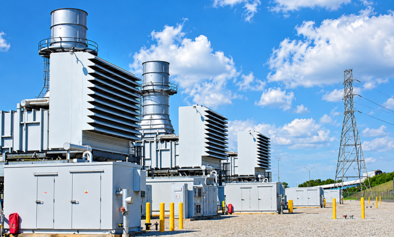
Gas-fired power generators operate under demanding conditions, where high temperatures, rotating machinery, electrical loads and continuous operation can gradually affect equipment performance. Regular inspections and accurate fault diagnosis help power plant operators reduce unplanned shutdowns, protect expensive components and maintain reliable electricity production.
Effective gas fired power generators repair involves more than replacing worn parts. Engineers need to identify the underlying cause of a fault, assess the condition of critical components and verify that repaired equipment meets the required operating standards. Mechanical balancing, material inspection and planned maintenance all contribute to this process.
Common Problems Found in Gas-Fired Power Generators
Gas-fired generating equipment can experience several mechanical and electrical problems during its service life. Bearings may wear due to lubrication issues, vibration can increase because of rotor imbalance, and thermal cycling may contribute to cracking or material fatigue. Electrical faults can also develop in windings, insulation systems and connections.


The symptoms often overlap. Excessive vibration, unusual noise, rising bearing temperatures and changes in electrical output may indicate different underlying faults. For example, vibration could result from rotor imbalance, shaft misalignment, bearing damage or looseness in the supporting structure.
Accurate diagnosis is therefore essential before repair work begins. Engineers typically review operating records, inspect affected components and use suitable diagnostic instruments to determine the source of the problem. This approach reduces unnecessary component replacement and helps prevent the same fault from returning after maintenance.
Why Gas-Fired Generator Maintenance Requires Careful Planning
Gas fired power generator maintenance should follow a planned schedule based on manufacturer recommendations, operating hours, start-stop cycles, equipment condition and the consequences of a potential failure.
Routine work may include checking lubrication systems, examining bearings and couplings, inspecting cooling arrangements, reviewing vibration readings and assessing electrical connections. More extensive inspections may require partial or complete equipment shutdown, depending on the generator design and the suspected defect.
Condition-based maintenance adds another layer of protection. By monitoring vibration, temperature, oil condition and electrical performance over time, maintenance teams can identify developing problems before they cause a major breakdown.
Maintenance records are particularly useful because gradual changes can reveal faults that a single inspection might miss. A rising vibration trend, for instance, may indicate a developing mechanical issue even when the machine remains within its immediate operating limits.
A well-planned maintenance programme also allows operators to organise spare parts, specialist technicians and testing equipment before a shutdown. This reduces avoidable delays and gives engineers enough time to complete inspections properly.
Low Speed Horizontal Balancing for Rotating Components
Rotor imbalance is a common source of vibration in rotating machinery. It occurs when the mass distribution around a rotating component is uneven, producing centrifugal forces that increase with rotational speed.
Low speed horizontal balancing is a technique used to assess and correct imbalance in suitable rotors while they rotate at relatively low speeds on a balancing machine. The rotor is supported horizontally, and measuring instruments detect vibration or force associated with its mass distribution.
Engineers use these measurements to determine the amount and location of corrective weight. Depending on the rotor design and balancing procedure, correction may involve adding material, removing material or adjusting designated balancing weights.
The method can be useful for compatible rotors, shafts and other rotating components during overhaul or refurbishment. However, low-speed balancing does not automatically establish acceptable behaviour at operating speed. Flexible rotors, complex rotor assemblies and equipment with speed-dependent vibration characteristics may require additional analysis or high-speed balancing.
Following balancing, technicians should check the results against the applicable acceptance criteria. Proper support conditions, accurate measurements and correct identification of the rotor are essential for obtaining reliable results.
Magnetic Part Testing for Detecting Surface Defects
Magnetic particle testing is a non-destructive testing method used to identify surface and near-surface discontinuities in suitable ferromagnetic materials. It can help engineers examine steel shafts, certain rotor components, couplings and other magnetic metal parts during maintenance.
The inspection process involves magnetising the component and applying suitable magnetic particles. If a crack or another discontinuity interrupts the magnetic field, local flux leakage can attract particles and create an indication that the inspector can evaluate.
The method is particularly useful for locating cracks around stress concentrations, keyways, shoulders and other areas exposed to mechanical loading. Detecting these defects early can help maintenance teams decide whether a component can remain in service, requires further examination or must be replaced.
Magnetic particle testing has limitations. It is not suitable for non-ferromagnetic materials such as aluminium, and it cannot reliably detect deep internal defects. Surface preparation, magnetisation direction, inspection conditions and the competence of the inspector all affect the results.
Where the material or suspected defect falls outside the method’s capabilities, another non-destructive testing technique should be selected.
Phased Array Volumetric Ultrasonic Testing for Internal Defects
Phased array volumetric ultrasonic testing uses multiple ultrasonic elements that can be electronically controlled to direct and focus sound beams through a material. By collecting measurements from different beam angles, inspectors can examine internal regions and assess indications that may not be visible on the surface.
For generator components, this technique may be appropriate for examining selected shafts, forged components, welds and other parts where internal discontinuities are a concern. It can help identify flaws such as cracks, inclusions and other material irregularities, depending on the component geometry and inspection procedure.
The results can provide information about an indication’s position, extent and orientation. This helps engineers assess whether further investigation or repair is necessary. Phased array inspection can also produce recorded scan data for review, traceability and comparison during later inspections.
Reliable results depend on appropriate calibration, probe selection, scanning coverage and evaluation criteria. Component geometry, material properties and access restrictions can affect inspection sensitivity. The technique should therefore be performed by qualified personnel using a procedure suited to the component and the applicable industry requirements.
Combining Inspection Results with Repair Decisions
No single inspection technique can identify every type of generator defect. A more reliable assessment combines visual examination, vibration analysis, dimensional checks and suitable non-destructive testing methods.
For example, vibration measurements may indicate a rotor problem, while balancing helps determine whether mass distribution contributes to the vibration. Magnetic particle testing can then examine suitable ferromagnetic surfaces for cracking, and ultrasonic methods can assess internal material conditions where required.
The combined findings help engineers distinguish between correctable imbalance, damaged components, alignment problems and material defects. This distinction matters because correcting one symptom without addressing its cause can lead to repeated failures.
Repair decisions should also consider component tolerances, manufacturer guidance, operating history and applicable acceptance standards. Any repaired component must undergo the necessary verification checks before the equipment returns to service.
Safety and Quality Checks Before Restarting
Before restarting a generator, maintenance teams should confirm that all repairs have been completed, fasteners and connections have been checked, protective guards are installed and tools or temporary equipment have been removed. Lubrication, cooling and other supporting systems must be ready for operation.
Where applicable, electrical testing, alignment verification, vibration measurements and controlled trial runs should follow approved procedures. Results should be documented so that future maintenance teams can compare the machine’s condition with established baseline values.
Work on gas-fired generating equipment also requires appropriate isolation, lockout procedures, control of ignition hazards and compliance with site safety rules. Testing and recommissioning should be managed by authorised personnel.
Building a More Reliable Generator Maintenance Programme
Successful gas fired power generators repair depends on accurate fault diagnosis, suitable repair methods and verification that the equipment is fit for service. Planned maintenance helps identify developing issues, while balancing and non-destructive testing provide valuable information about rotating components and material condition.
By using low-speed balancing where appropriate, applying magnetic particle testing to compatible materials and selecting phased array ultrasonic inspection for suitable internal examinations, power plant operators can make better-informed maintenance decisions. Consistent documentation and post-repair testing further support equipment reliability, personnel safety and long-term operating performance.