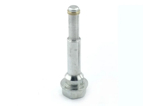
When a linear axis starts to lose accuracy, attention usually goes to the bearings or the drive first. The part which often decides the result sits underneath them. Well-specified guide rods give a moving carriage both a smooth running surface and firm structural support, so your machine repeats the same path cycle after cycle.
A rod which looks correct on paper can still bend under a heavier tool or run rough against a bearing. Choosing guide rods by diameter, span, working load and surface quality together gives your axis the stiffness and smoothness it needs from day one. Keep on reading to know more about how each factor shapes linear motion.
A Guide Rod Carries the Bearing and the Moving Load at Once
One Rod Doing Two Jobs: A guide rod acts as the hardened running surface for a linear bearing and as a structural beam which holds the moving assembly in position. The balls inside a linear bushing roll directly on the rod, so its surface takes the contact stress. The same rod also resists bending from the carriage, the tooling and any process force.


Diameter and Span Govern Deflection: For an end-supported rod, deflection rises with the cube of the unsupported span and falls with the fourth power of the diameter. So a modest increase in diameter brings a large gain in stiffness. The modulus of elasticity stays much the same across common steel grades and heat treatments, which is why geometry usually decides how far a rod bends.
See also: Granny Flats Port Macquarie for Comfortable Extra Living Space
Correct Rod Sizing Keeps the Carriage on Its Intended Path
Working Load Defines Carriage Accuracy: A carriage keeps its intended path when rod deflection under the full working load stays within the tolerance the process can accept. Longer rods need a larger diameter or intermediate support to hold that limit. When deflection stays small, parts leave the machine with consistent dimensions and operators make fewer manual corrections.
Postponed Upgrades Narrow Later Choices: In everyday maintenance practice, engineers often see machines where a rod sized for the original tooling was kept after a heavier head was fitted, and accuracy drifted gradually. If the change waits, the extra load tends to reach bearings, housings and seals as well. The eventual fix then involves more parts and longer downtime than an early rod upgrade would.
Surface Quality and Geometry Support Lasting Linear Accuracy
Straightness and Roundness Keep Ball Contact Even: A linear bearing runs smoothly when its balls meet the rod with steady contact along the full stroke, which depends on straightness and roundness. A rod with a slight bow changes running clearance along its length, so friction and positioning shift. Good roundness lets every ball row share the load, and an h6 or g6 diameter tolerance controls the fit.
Hardness and Finish Protect the Running Surface: A hardened and precision-ground surface lets rolling balls travel along the rod without indenting it. Linear shafts are commonly induction hardened on the outer layer, while the core stays tougher. Bearing makers generally lower the rated load for softer shafts. Fewer bearing changes also support better overall equipment effectiveness across the service life of the machine.
Round Rods and Profile Rails Suit Different Machine Demands
Comparing Linear Guidance Options: End-supported round rods suit moderate loads and shorter spans, and with self-aligning bearings they accept small mounting misalignments. Fully supported rods with open bearings extend usable length and stiffness at a slightly higher cost. Profile rail guides offer higher load ratings and rigidity, though they need precisely machined mounting surfaces and usually cost more to buy and install.
Where Precision Rods Make Practical Sense: For packaging lines, pick-and-place units, test rigs and light machine tool axes, guide rods offer a practical balance between accuracy and installation cost. They also suit frames which are difficult to machine perfectly flat. If loads grow or rigidity targets tighten later, a supported rod or a profile rail may then become the better next step.
Selection Points for Machinery with Repeatable Linear Movement
A Checklist for Specifying Linear Shafts: A clear specification helps your design and purchasing teams order the right rod the first time. When you specify guide rods for controlled, repeatable movement, the points below cover both the structural side and the running surface. Share them with your supplier early, so quotes and drawings line up before production begins.
- Rod diameter should be checked against the unsupported span and the full working load.
- Intermediate or continuous support can extend usable length where a larger diameter will not fit.
- Straightness per metre and the diameter tolerance class should appear clearly on the drawing.
- Surface hardness should match the bearing maker’s recommendation so the full rated load applies.
- A ground and polished finish supports smooth travel and longer seal life.
- Stainless or chrome-plated rods suit washdown areas and humid environments.
Steady Motion Starts with the Right Rod Specification
Load capacity and linear precision come from the same set of choices, and correctly chosen guide rods bring them together in one component. When diameter, span, straightness and hardness suit the application, your carriage holds its path and your bearings run smoothly. Your team gets predictable cycle times, and your maintenance plan becomes easier to follow.
Leaving an undersized or softer rod in place usually leads to a larger repair later, with more parts and more downtime involved. Reviewing the specification now keeps the change simple and planned. Share your drawing, stroke length and working load, and get in touch today to discuss precision linear shafts for your machinery.